![]()
Strength / Gear Tooth Bending Stress
Authors: Tugan Eritenel
Description: Calculation of root bending stress in spur gears.
Introduction
This chapter is on the root bending stress of parallel axis gears.
Contributors to Root Stress
A gear tooth can be modeled as a cantilever beam under load. Gear tooth bending was first investigated by Wilfred Lewis, and the bending stress equation is referred as the Lewis formula. The figure below shows the three types of stress acting on the gear tooth. These are:
- Bending stress
- Compressive stress
- Shear stress
Bending stress is calculated as:
$$\sigma_b = \frac{\textrm{Bending moment}}{\textrm{Section modulus}} = \frac{F_N \cos\alpha_a\prime}{\frac{1}{6} b S_q^2}$$Compressive stress is calculated as:
$$\sigma_c = \frac{F_N \sin\alpha_a\prime}{b S_q}$$Shear stress is calculated as:
$$\tau_m = \frac{\cos\alpha_a\prime}{b S_q}$$where $S_q$ is the thickness of the weakest part at the root, anfd $\alpha_a \prime$ is the pressure angle at the tip corner. Research has shown that almost all stress at the gear tooth root is from bending, and the contribution of shear stress and compressive stress can be neglected.
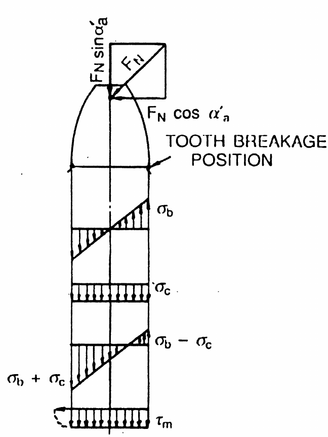
Stresses on gear tooth.
Image credit: G. M. Maitra, Handbook of Gear DesignRoot Bending Stress Calculation
The bending stress is organized as:
$$\sigma_b = \frac{F_t}{b m_n} \frac{6m_n h_q \cos\alpha_a \prime}{S_q^2 \cos\alpha}$$The second fraction is defined as the tooth form factor according to:
$$q_k = \frac{6m_n h_q \cos\alpha_a \prime}{S_q^2 \cos\alpha}$$where values for $q_k$ are obtained from the figure below.
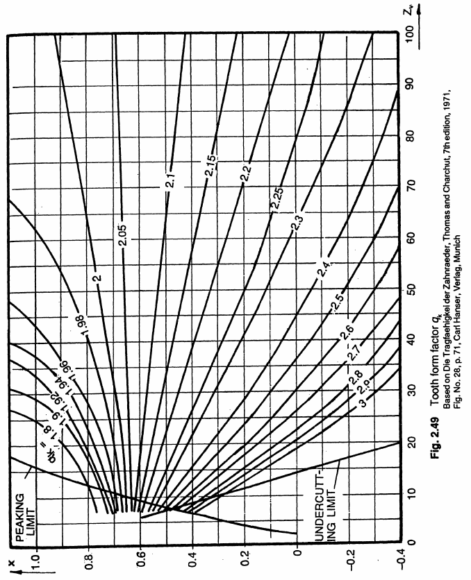
Tooth form factor for bending stress.
Image credit: G. M. Maitra, Handbook of Gear DesignThe final form of the tooth bending stress is,
$$ \sigma_{b} = \frac{F_t}{b_1 m_n} q_e q_k$$where $F_t$ is the tangential gear mesh force, $b_1$ is the facewidth of the pinion, $m_n$ is the normal module, $q_e = \frac{1}{CR}$ is a factor from contact ratio, and $q_{k,1}$ is the tooth form factor of the pinion obtained from the figure above.
Tangential force acting on the gear tooth is found from the torque on the pinion, using
$$ F_t = \frac{T_1}{\frac{1}{2}d_{p,1}}$$The permissible root bending stress is denoted by $\sigma_{bp}$ for the material. For example, the permissible bending stress for induction hardened steel 40 Cr 4 is given as 200 MPa. The stress at the root must be less than the permissible bending stress, $\sigma_b < \sigma_{bp}$. Substituting this and the tangential force expression, and using milimeters for units for facewidth and module gives the minimum module as,
$$ m > \sqrt[3]{\frac{2000 T_1 q_e q_k }{\frac{b_1}{d_{p,1}}z_{1}^2 \sigma_{bp}} }$$Idential expression with the parameters for the wheel gives the root stress on the wheel. Generally, root stress on pinion is higher than the wheel.
Example | Root Bending Stress
GIVEN
- A gear pair has 45 teeth on the pinion.- Torque on the pinion is 600 Nm.
- Pinion material has permissible bending stress of 200 MPa.
FIND
1) Minimum module so that the pinion is safe for bending.2) Bending stress on pinion tooth root.
SOLUTION
For the first design iteration, contact ratio is taken as 1, $q_e = 1$. Tooth form factor is $q_k = 2.4$, assuming profile shift is not applied. The ratio of facewidth to pitch diameter is taken as $b_1 / d_{p,1} = 0.5$ to provide a starting point for the design. The formula above is used for finding the minimum module. Substituting the given values, the minimum module for bending is:$$ \sigma_{b} = \frac{F_t}{b_1 m_n} q_e q_k$$ where the pitch diameter is $d_{p,1} = m_n z_1$, facewidth is $b_1 = 0.5 d_{p,1}$, and tangential force is $F_t = 2 T_1/d_{p,1}$. Substituting the values,
Conclusion
This notebook documents the procedure to find spur gear root bending stress. Inputs are a few parameters from gear macro geometry: number of teeth, pressure angle, and applied torque. Minimum module is found so that the gears are safe considering root bending stress. For a chosen module and the gear parameters above, root bending stress is calculated.
Learn More
Continue reading the Drivetrain Hub | Notebook Series to learn more about the design and analysis of spur gears and other gear types.
Model Gear Root
Accurately model the gear tooth root with the Drivetrain Hub | Gears App, a modern drivetrain modeling environment 100% online at drivetrainhub.com.
Improve Notebook
Our gear geometry notebooks are publicly hosted in a GitHub repository, available for anyone to view and propose edits.
References
- G. M. Maitra, (1994), "Handbook of Gear Design", Tata McGraw-Hill