![]()
Geometry / Planetary Gears
Authors: Chad Glinsky
Description: Review the geometric design of planetary geartrain layouts.
Introduction
The geometry of planetary geartrain layouts is reviewed here. Planetary geartrains can be configured in several ways, with the most common architectures reviewed here. Attractive characteristics of planetary geartrains include:
- Mechanical power is transferred between concentric bodies (ring, sun, carrier)
- Power density is high, providing great mechanical power in a small package
- Multiple gear meshes act on central bodies, with self-centering tendencies
- Planet gears may precess with the carrier reference frame
- Cylindrical involute gears are used to transmit motion
- Multiple power inputs or outputs can be defined
The visualization of a planetary geartrain clearly demonstrates its unique geometric characteristics.
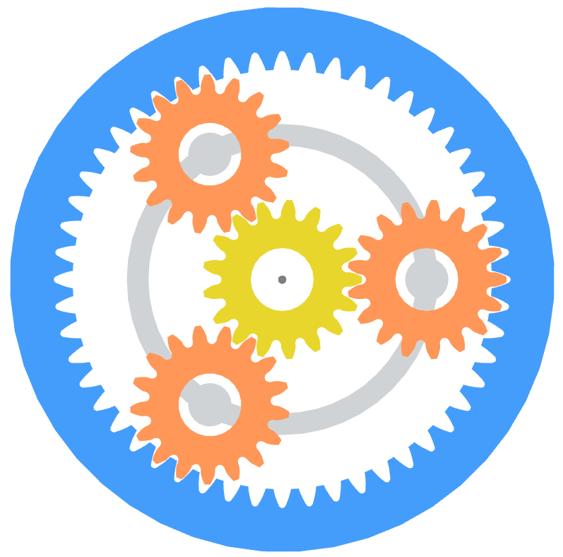
Planetary geartrain modeled in Gears App
Most commonly, planetary geartrains have a sun gear (yellow), ring gear (blue), and multiple planet gears (orange) on a carrier (gray). Spur or helical gears are used for a planetary gearset, with each type having advantages. This notebook reviews the unique geometric attributes of planetary gears and their significance to planetary gear mesh operation.
The various conditions that must be satisfied for a planetary geartrain to successfully assemble are reviewed in this notebook. To understand the geometry of the spur or helical gears that makeup a planetary geartrain, see the respective notebooks on gear geometry.

Nomenclature 
This table provides a set of parameters commonly used to define the geometry of planetary geartrains.
| Symbol | Description |
|---|---|
| $i$ | Transmission ratio |
| $u$ | Base ratio |
| $\omega$ | Angular velocity |
| $m_n$ | Normal module |
| $z$ | Number of teeth |
| $\beta$ | Helix angle |
| $d_a$ | Tip diameter |
| $p_t$ | Transverse pitch |
| $d_w$ | Pitch diameter |
| $a$ | Center distance |
| $l$ | Planet distance |
| $N$ | Number of planets |
Ratios 
When designing a planetary geartrain, a transmission ratio is typically used to define a target or goal. The design space is largely determined from the target ratio, so an allowable deviation is often used depending on the application requirements. The general equation for transmission ratio is expessed as:
$$i = \frac{\omega_\text{in}}{\omega_\text{out}}$$A base ratio is defined as the transmission ratio between the sun and ring gear, with a fixed carrier. This is effectively an idler geartrain, with the planets behaving as idler gears. The ratio is calculated as:
$$u = \frac{z_3}{z_1}$$where sign convention for number of ring gear teeth, $z_3$, is negative. The transmission ratio between the sun gear and carrier, with the ring gear constrained to ground, is expressed as:
$$i_{1V} = 1 - u$$Additionally, the transmission ratio between the carrier and ring gear, with the sun gear constrained to ground, is expressed as:
$$i_{3V} = 1 - \frac{1}{u}$$Other transmission ratios of interest may be solved for by rearranging the equations above.
To learn more about the fundamentals of rotational kinematics and how gears transfer motion, refer to our kinematics notebook. The current notebook is focused on planetary design layouts.
Constraints
To design a valid planetary geartrain, one that can be assembled and operate in real-world applications, multiple constraints must be adhered to. All the constraints relate to geometrical relationships of planetary geartrains.
As will be shown, only certain combinations of tooth counts, planet count, and planet spacing are possible.
Center Distance
The geometric condition that requires the center distance for the sun-planet and planet-ring gear meshes to be the same is obvious when illustrated. The equation to express this relationship can be expanded as a function of the working pitch diameters:
$$\lvert a_{12} \rvert = \lvert a_{23} \rvert$$$$\lvert d_{w1} + d_{w2} \rvert = \lvert d_{w2'} + d_{w3} \rvert$$where $d_{w2'}$ specifically refers to the working pitch diameter of the planet-ring gear mesh, which may differ from the sun-planet mesh due to profile shifts, tooth counts, and center distance differing from nominal (a condition with zero profile shift or backlash). Below illustrates a layout diagram for a 4-planet geartrain:

Planetary layout diagram of 4-planet geartrain
When considering the detailed tooth form of the meshing gears, this means multiple values of planet tooth count are possible for a given design. The design space is somewhat complicated by this, but it is more applicable to the detailed tooth design, so does not require immediate consideration.
Planet Interference
Upon viewing the enveloping geometry, notice the condition of planet-to-planet interference must be considered. Clearance must exist between the tip diameters of each planet. The equation to express this constraint is:
$$l > d_{a2}$$where $l$ is the center distance between planets, expressed as:
$$l = 2a\sin\left(\frac{\pi}{N}\right)$$Meshing Teeth
Despite a given enveloping diagram appearing as a valid design, remember that an integer number of teeth is required for all the gears. Adding to this requirement, the teeth of each planet must mesh with both the sun and ring. Determining valid conditions for teeth to mesh depends on the tooth counts, number of planets, and planet spacing.
To understand this requirement, let's imagine assembling a planetary geartrain. First, position the sun at the origin with any angle of rotation. Next, add the first planet to a desired carrier position, rotating its teeth to mesh with the sun. Then, position the ring at the origin, rotating its teeth to mesh with the planet. Now, imagine adding the second planet somewhere on the carrier, not being allowed to rotate the sun or ring. Only certain carrier positions will allow the second planet to mesh with both the sun and ring.
Equal Spacing
For equally-spaced planets, the following equation is used to identify valid meshing conditions for a given number of planets and tooth counts:
$$k = \frac{z_1 - z_3}{N}$$where $k$ must be an integer for the gears to mesh.
Unequal Spacing
It is also possible for the gears to mesh with unequal planet spacing. In such cases, the smallest angular unit pertaining to the allowable planet positions is used to find the planet positions nearest equal spacing. This unit angle of planet position, or so-called tick angle, may be calculated as:
$$\hat{\theta} = \frac{2 \pi}{z_1 - z_3}$$Typically, unuequal spacing is only used in 4-planet geartrains where the planet gears can be positioned with diametrically-opposed spacing. Sometimes this is called an X configuration. A diametrically-opposed design is allowed if the remainder of $k$ is 0.5. Designs capable of being equally-spaced can also be modified to be diametrically-opposed.
Mesh Phasing
Once the geometric conditions are met to ensure a valid planetary geartrain can be assembled, it is also of interest to consider the phasing of the planetary gear meshes. Phasing refers to the cyclic behavior of multiple gear meshes with the same frequency.
Three types of planetary phasing exist for nominal conditions.
- In-phase
- Sequential-phase
- Counter-phase
Before explaining each phasing type, it must understood that phasing specifically refers to the phase angle for the harmonics of gear mesh excitation caused by imperfect conjugate action, commonly referred to as transmission error. These excitations are caused by numerous things, including manufacturing and assembly errors, but also due to the deflection of gear teeth under operating loads.
Fourier transform is used to analyze a time signal as a series of sinusoids, useful for harmonic analysis.
Phase Angles
To understand the different types of planetary phasing, we must first consider the phasing of each gear mesh in the planetary geartrain. Let's individually examine the gear meshes for the ring and sun.
Planet-Ring
To determine the phase angle of a planet-ring mesh, we must define a relationship between the position of ring gear teeth and the position of the planet gear, e.g. equally-spaced or diametrically-opposed. Successive ring gear teeth are separated by the ring transverse pitch angle, defined as:
$$\psi_{t3} = \frac{2 \pi}{z_3}$$By writing a fraction that divides the $i^\text{th}$ planet angle by the ring transverse pitch angle,
$$q_{3i} = \frac{\theta_i}{\psi_{t3}}$$the mesh phase angle is determined by the remainder of $q_{3i}$, the fraction of mesh cycle, according to:
$$\phi_{3i} = 2 \pi * (q_{3i} \bmod 1)$$Sun-Planet
Following a similar logic as above, we can compute the sun-planet gear mesh phase angles as with equations:
$$\psi_{t1} = \frac{2 \pi}{z_1}$$$$q_{1i} = \frac{\theta_i}{\psi_{t1}}$$$$\phi_{1i} = 2 \pi * (q_{1i} \bmod 1)$$Phasing Types
The phasing classification for a planetary geartrain is based on the first harmonic of its gear mesh excitations. Higher harmonics may have different phasing. The following equation can be used to determine phasing with equally-spaced planets:
$$k_\phi = |z_3| \bmod N$$In particular, the phasing is of interest to understand which gear mesh excitations reinforce or cancel in the system. Excitation reinforcements and cancellations are studied for the following summed components:
- Torques and axial forces, i.e. thrusts (helical only)
- Radial forces
In-Phase
In-phase refers to having the same phase angle for each gear mesh. In-phase planetaries have reinforced torques and thrusts but cancelled radial forces. The condition for in-phase is:
$$k_\phi = 0$$Sequential-Phase
Sequential-phase refers to having equally separated phase angles for subsequent gear meshes. Sequential-phase planetaries have cancelled torques and thrusts but reinforced radial forces. The condition for sequential-phase:
$$k_\phi = 1, N-1$$Counter-Phase
Counter-phase refers to having opposite phase angles for opposing planets. Counter-phase planetaries have all summed components of excitation cancelled. The condition for counter-phase is:
$$k_\phi = 2, 3, \dots, N-2$$Mixed-Phase
Mixed-phase refers to having a combination of phasing types. This can only occur with unequally-spaced planets, as found in diametrically-opposed designs. In such cases, the gear mesh phase angles must be calculated and used in the sum of harmonics to determine which reinforcements and cancellations occur.
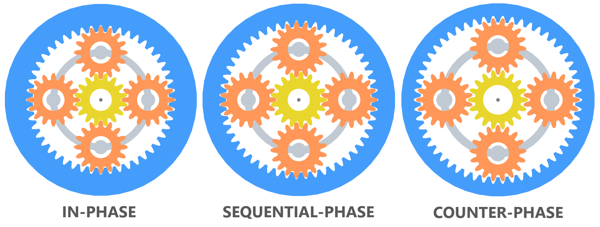
Planetary geartrain phasing types modeled in Gears App
Errors caused by manufacturing, assembly, and operation can cause gear mesh phasing deviations and low frequency modulations that will lead to more vibration frequencies, increased vibrations, and undesireable noise characteristics. Planetary phasing should be considered during the design-phase.
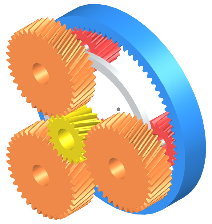
Helical Gears
To extend the planetary design rules to helical gearing, we need to consider the helix angle and the transverse geometric properties, such as module and pitch diameters. The transverse module of a helical gear is most easily understood as the millimeters of theoretical pitch diameter per tooth:
$$m_t = \frac{d}{z}$$which can be expressed as a function of the normal module and helix angle according to:
$$m_t = \frac{m_n}{\cos\beta}$$It can be deduced from the equations above that for a given normal module and number of teeth, increasing the helix angle causes an increase in theoretical pitch diameter. This is important to consider for planetary layout design.
Phasing
For the fundamentals of planetary phasing, the introduction of a helix angle does not change a lot. The concept is still the same, i.e. each planetary gear mesh produces a dynamic signal at the mesh frequency and these signals may cancel or reinforce in various ways. Since a helix angle introduces axial forces into the gear mesh, it may also be considered in the cancellations and reinforcements.
- The sum of axial forces cancel / reinforce the same as torques.

Nomenclature 
This table provides a set of parameters commonly used to define the geometry of compound planetary geartrains.
TODO need to add parameters pertaining to the planet gear / pinion
| Symbol | Description |
|---|---|
| $i$ | Transmission ratio |
| $u$ | Base ratio |
| $\omega$ | Angular velocity |
| $m_n$ | Normal module |
| $z$ | Number of teeth |
| $\beta$ | Helix angle |
| $d_a$ | Tip diameter |
| $p_t$ | Transverse pitch |
| $d_w$ | Pitch diameter |
| $a$ | Center distance |
| $l$ | Planet distance |
| $N$ | Number of planets |
Ratios 
TODO define ratios for compound planetary.
Constraints 
TODO define constraints for compound planetary design.
TODO Solution for compound planetary.
Model Gears
Gears App software is used to accurately model, analyze, and build planetary geartrains entirely in your web browser.
Learn More
Notebook Series is free to learn and contribute knowledge about gears, such as geometry, manufacturing, strength, and more.
Edit Notebook
GitHub repos are used to publicly host our notebooks, allowing anyone to view and propose edits.
References
- Gears and Gear Drives, 1st Edition. Damir Jelaska
- Handbook of Practical Gear Design and Manufacture, 1st Edition. Darle W. Dudley