![]()
Geometry / Spur Gears
Authors: Tugan Eritenel
Description: Geometry of spur gears, given constraints on ratio, center distance, and clearances.
Involute function, pressure angle, and tooth thickness functions.
def inv(a):
    return math.tan(a) - a

def alpha_at_given_d(d,d_b):
    return math.acos(d_b/d)

def thickness_at_given_d(d,d_p,d_b,alpha,m,x):
    S_p = math.pi/2*m + 2*m*x*math.tan(alpha)
    alpha_d = alpha_at_given_d(d,d_b)
    S = d*(S_p/d_p+inv(alpha)-inv(alpha_d))
    return S
Definitions
The table below shows the definitions of basic gear geometry paramaters, and equations needed to calculate them.
| Parameter | Expression | Units |
| Involute function | $\rm{inv}\left({\theta}\right) = \tan\theta - \theta $ | rad |
| Number of gear teeth | $z$ | None |
| Normal module | $m$ | mm |
| Generating pressure angle | $\alpha$ | deg |
| Profile shift | $x$ | $m$ |
| Addendum modification | $y$ | $m$ |
| Pitch diameter | $d_p = mz$ | mm |
| Base diameter | $d_b = d_p \cos \alpha$ | mm |
| Tip diameter | $d_t= d_p + 2m\left(1+x-y\right)$ | mm |
| Root diameter | $d_r= d_p + 2m\left(-1.25+x\right)$ | mm |
| Base pitch | $B_p= m\pi\cos\alpha$ | mm |
In a gear pair, parameters that belong to the first gear are indicated with subscript 1, and parameters that belong to the second gear are indicated with subscript 2. The gear with the lower number of teeth is referred to as the "pinion", and the gear with the higher number of teeth is referred to as the "wheel". The term "working" refers to the parameters when the gear pair is operating at a given center distance.
| Parameter | Expression | Units |
| Standard center distance | $a_0 = m\frac{z_1 + z_2}{2}$ | mm |
| Operating center distance | $a$ | mm |
| Working pressure angle | $\alpha_w = \cos^{-1}\left( \frac{a_0}{a} \cos\alpha \right) $ | mm |
| Working pitch diameter | $d_w = \frac{d_b}{\cos\alpha_w}$ | mm |
| Contact ratio | $R = \frac{\frac{\sqrt{d^2_{t,1} -d^2_{r,1}} + \sqrt{d^2_{t,2} -d^2_{r,2}}}{4} -a\sin\alpha_w} {B_p}$ | None |
Parameters and expressions on tooth thickness, backlash, and tip-to-root clearances are given in table below.
| Parameter | Expression | Units |
| Circular tooth thickness at pitch diameter | $S_p = \frac{m}{2}\pi + 2mx\tan\alpha$ | mm |
| Pressure angle at a given diameter, $d$ | $\alpha(d) = \cos^{-1}\left(\frac{d_b}{d} \right)$ | mm |
| Circular tooth thickness at a given diameter, $d$ | $S(d) = d\left( \frac{S_p}{d_p} + \rm{inv}\alpha - \rm{inv}\alpha_d \right)$ | mm |
| Circular backlash | $B_c = \frac{B_p}{\cos\alpha_w} - S\left(d_{w,1}\right) - S\left(d_{w,2}\right)$ | mm |
| Linear backlash | $B_l = B_c \cos\alpha_w$ | mm |
| Pinion tip to gear root clearance | $c_1 =a - a_0 - m\left(x_1+x_2 - y_1 \right)$ | mm |
| Gear tip to pinion root clearance | $c_2 =a - a_0 - m\left(x_1+x_2 - y_2 \right)$ | mm |
Profile Shift
Hob can be pushed or pulled while gears are manufactured. This affects the shape of the gear tooth generated. A positive profile shift indicates that the hob is pulled away from the gear center.
Advantages of Positive Profile Shift
- Reduces or eliminates undercut
- Reduces root stress by increasing tooth thickness
- Improves radius of curvature at contact
Disadvantages of Positive Profile Shift
- Reduces tooth tip thickness, can lead to peaking
- Can reduce contact ratio
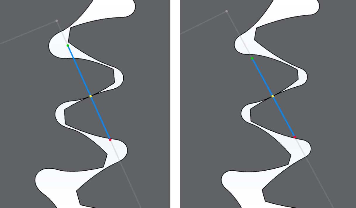
Negative (left) and positive (right) profile shifts in Gears App
Undercut
Involute profile is not defined below the base circe. Undercut occurs when tool tip corner does not cut the transition point between the root fillet and the involute profile. Undercut which increases stress concentration. Undercut is generally to be avoided or reduced if possible. Gears with low number of teeth are more prone to undercut.
The minimum number of gear teeth without undercut is given by,
$$ z_{min} = \frac{2}{\sin^2\alpha}$$where $\alpha$ is the pressure angle of the hob. Given the number of teeth, the minimum profile shift required to avoid undercut is given by,
$$x=\frac{z_{min} - z}{z_{min}}$$
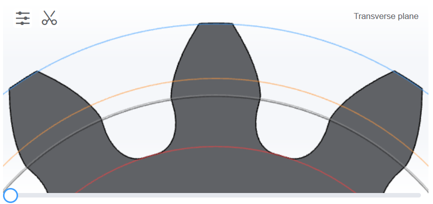
Spur gear undercut in Gears App
Addendum Modification
To avoid peaking and/or tip-to-root interference, tooth addendum is reduced. No actual tooth are cut off after the gears have been made, but the blank diameter itself is reduced before manufacturing.
Peaking
Peaking occurs when the gear tooth tip thickness reaches zero due to positive profile shift. Generally it is recommended that the tip thickness is greater than $0.25 m$, where $m$ is the normal module.
Tip-to-Root Interference
Tip-to-root interference occurs when the gear teeth are too long and interfere with the root of the mating gear due to positive profile shift. Generally, it is recommended that tip-to-root clearance is equal to or greater than $0.25m$.
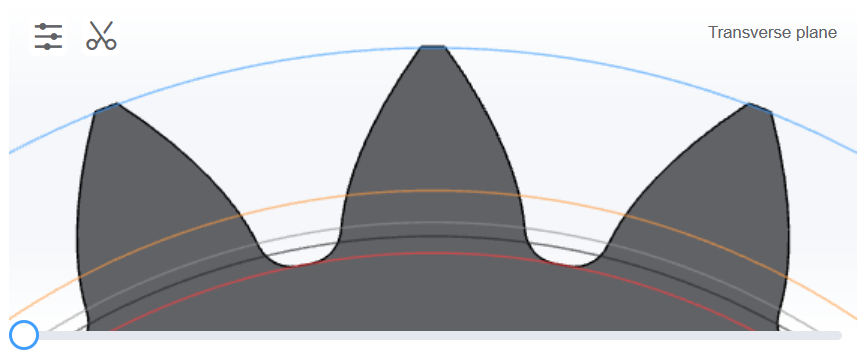
Near peaking spur gear in Gears App
Design Process
The geometric design process is explained by means of an example. Requirements are as follows:
alpha=df_requirements["Common"]["Standard pressure angle"]/180*math.pi
i_required = df_requirements["Common"]["Ratio"]
i_tol = df_requirements["Common"]["Ratio tolerance"]
m = df_requirements["Common"]["Module"]
a = df_requirements["Common"]["Working center distance"]
B_req = df_requirements["Common"]["Backlash"]
Choosing Number of Teeth
In this notebook, the aim of design is to minimize the size of the gears. To that end, the lowest number of teeth possible within limits should be chosen. For a first design iteration, the minimum acceptable number of teeth is chosen to avoid undercut without profile shift, given by $z_{min} = \frac{2}{\sin^2\alpha}$. The number of teeth can be reduced by one or two in the following design iterations, if profile shift eliminates undercut.
The selected number of teeth should also satisfy the required gear ratio within a given tolerance. Since gear ratio is defined by $i=\frac{z_2}{z_1}$, rearranging gives $z_2=i z_1$. Number of teeth on the wheel is found using the minimum number of teeth for the pinion. If the actual gear ratio is not within tolerance, the number of teeth on the pinion is incremented, and the process is repeated until the actual gear ratio is within tolerance. The following code automates this process.
z_1 = 2/(math.sin(alpha)**2)
z_1 = int(round(z_1))
z_2 = int(round(z_1*i_required))
print(z_2)
i = z_2/z_1
iteration_count=0
max_iter = 400
while abs(i - i_required)>i_tol:
    z_1=z_1+1
    z_2 = int(round(z_1*i_required))
    i = z_2/z_1
    iteration_count=iteration_count+1
    if iteration_count>max_iter:
        print("ERROR: Iteration count of " +str(200) + " exceeded, increase ratio tolerance.")
        break

display.display(HTML('<div class="alert alert-block alert-info">Pinion number of teeth, $z_1$ = ' + str(z_1) + '</div>'))
display.display(HTML('<div class="alert alert-block alert-info">Wheel number of teeth, $z_2$ = ' + str(z_2) + '</div>'))
display.display(HTML('<div class="alert alert-block alert-info">Actual gear ratio, $i$ = ' + str(round(i,3)) + '</div>'))
display.display(HTML('<div class="alert alert-block alert-info">Required gear ratio, $i_{\\rm{required}}$ = ' + str(round(i_required,3)) + '</div>'))
Calculate Profile Shift
Once the number of teeth is known, the standard center distance is calculated by $a = m\frac{z_1+z_2}{2}$
Since the operating center distance is specified as a requirement, the working pressure angle is found using $\alpha_w = \cos^{-1}\left(\frac{a_0}{a\cos\alpha}\right)$
a_0 = m*(z_1+z_2)/2
alpha_w = math.acos(a_0/a*math.cos(alpha))
display.display(HTML('<div class="alert alert-block alert-info">Standard center distance, $a_0$ = ' + str(a_0) + '</div>'))
display.display(HTML('<div class="alert alert-block alert-info"> Working pressure angle, $\\alpha_w$ =' + str(round(alpha_w*180/math.pi,3)) + ' deg </div>'))
Usually, the standard center distance does not equal the required center distance, which may be dictated by other design restrictions such as packaging or manufacturing. Generally the gear tooth numbers are chosen such that the operating center distance is greater than the standard center distance; this is called extended center distance.
If the gears operate at extended center distance without profile shift, undesirable large backash will result and the contact ratio may be too low. For these reasons, profile shift is applied such that the only source of backlash is the thinning of the hob. Whether or not the centers are extended, any undercut on the pinion may be removed by moving the profile shift to the gear.
The total profile shift needed is found by,
$$x_1 + x_2 = \frac{\left(z_1+z_2\right) \left(\rm{inv}\alpha_w -\rm{inv}\alpha\right)}{2\tan\alpha}$$x_total = (z_1 + z_2)*(inv(alpha_w) - inv(alpha))/2/math.tan(alpha)
The equation above results in gears with zero backlash excluding what is built into the hob. If a specified curcular backlash is required, the total profile shift can be updated by,
$$x_{mod} = -\frac{B_{c,req}}{2 m \tan\alpha} \frac{\cos\alpha_w}{\cos\alpha}$$which modifies the total profile shift by,
$$ \left(x_1 + x_2 \right)_{\rm{new}}= x_1+x_2 + x_{mod}$$x_mod = -B_req/(2*m*math.tan(alpha))*math.cos(alpha_w)/math.cos(alpha)
display.display(HTML('<div class="alert alert-block alert-info"> Reduction in profile shift to obtain the required backlash, $x_{mod}$ = ' + str(round(x_mod,3)) + '</div>'))
Distributing Profile Shift
The sum of profile shift needed for the gears to operate at the required center distance can be distributed in any way between the pinion and the gear. However, a few empirical equations help improve the design.
For reduced sliding velocity, $$x_1 \approx \frac{x_1+x_2}{i+1}+\frac{i-1}{i+1+0.4 z_2}$$
For equal root stress, $$x_1 \approx \frac{x_1+x_2}{i+1}+\frac{1}{2}\left(\frac{i-1}{i+1}\right)$$
For equal contact pressure, $$x_1 \approx \frac{x_1+x_2}{i+1}\frac{z_1+12}{z_1+2} + \frac{8}{z_1+2}$$
Using the formula for equal root stress,
x_total = x_total + x_mod
display.display(HTML('<div class="alert alert-block alert-info"> Total profile shift, $x_1 + x_2$ = ' + str(round(x_total,3)) + '</div>'))
x_1 = x_total / (i + 1) + 0.5 * (i - 1) / (i + 1)
x_2 = x_total - x_1

display.display(HTML('<div class="alert alert-block alert-info"> Pinion profile shift, $x_1$ = ' + str(round(x_1,3)) + '</div>'))
display.display(HTML('<div class="alert alert-block alert-info"> Wheel profile shift, $x_2$ = ' + str(round(x_2,3)) + '</div>'))
Calculate Addendum Modification
The tip-to-root clearance is found using the equation, for the pinion and gear respectively,
$$c_1 =a - a_0 - m\left(x_1+x_2 - y_1 \right)$$$$c_2 =a - a_0 - m\left(x_1+x_2 - y_2\right)$$Find required addendum modification, if needed, so that tip-to-root clearance is at least $0.25m$, using,
c_req = 0.25
y = c_req + x_total - (a - a_0) / m
y_1 = y
y_2 = y

if y > 0:
    display.display(HTML('<div class="alert alert-block alert-info">Addendum modification, y = ' + str(round(y,3)) + ' is applied<br>This is a reduction in addendum</div>'))
elif y <= 0:
    display.display(HTML('<div class="alert alert-block alert-info">Addendum modification, y = ' + str(round(y,3)) + ' is applied<br>This is an increase in addendum</div>'))
Checks
This section lists parameters that needs to be checked to make sure the outputs of the design are within limits. If a parameter does not satisfy the requirements, then the design needs to be updated.
CHECK: Undercut in pinion and wheel
After profile shift is applied, check for undercut pinion and wheel. Undercut occurs if,
$$x_1 < \frac{z_{min}-z_1}{z_{min}} \quad \text{where } z_{min} = \frac{2}{\sin^2\alpha}$$CHECK: Top Land (Tooth Tip Thickness)
The equation for pinion tooth tip thickness is given by,
$$ S_{t,1} = d_{t,1}\left( \frac{S_p}{d_p} + \rm{inv}\alpha - \rm{inv}\alpha_{t,1} \right) $$where, tooth thickness at pitch circle is given by,
$$S_p = \frac{m}{2}\pi + 2mx\tan\alpha$$where, pressure angle at tooth tip is given by,
$$\alpha_{t,1} = \cos^{-1}\left(\frac{d_b}{d_{t,1}} \right)$$The equations for gear tooth tip thickness are identical with appropriate subscripts representing parameters for the gear.
Check that pinion and wheel tooth tip thickness is at least $0.25m$.
CHECK: Backlash
Backlash required can be found in IS:4460. For low speed gears where pitch line velocity is below 8 m/s, maximum backlash for $m=2$ mm is 0.13 mm, for $m=8$ mm, is 0.4mm. For higher speed gears where pitch line velocity is above 8 m/s, maximum backlash for $m=2$ mm is 0.18 mm, for $m=8$ mm, is unchanged at 0.4mm.
Check backlash below. Note that the backlash calculated here should match the specified backlash $B_{req}$.
CHECK: Contact Ratio
Contact ratio should be above 1.1 to ensure contact is maintained at all times. Contact ratio is found from tip and root diameters as given by the equation
$$R = \frac{\frac{\sqrt{d^2_{t,1} -d^2_{r,1}} + \sqrt{d^2_{t,2} -d^2_{r,2}}}{4} -a\sin\alpha_w} {B_p}$$CHECK: Tip-to-Root Clearance
Calculate tip-to-root clearance. Note that this should match the required clearance, since addendum modification is calculated to maintain $0.25m$ clearance.
c_1 = a - a_0 - m * (x_1 + x_2 - y_1 )
c_2 = a - a_0 - m * (x_1 + x_2 - y_2 )

display.display(HTML('<div class="alert alert-block alert-info">Clearance, $c_1/m$ = ' + str(c_1/m) +'</div>'))
display.display(HTML('<div class="alert alert-block alert-info">Clearance, $c_2/m$ = ' + str(c_2/m) +'</div>'))
The following table summarizes the gear geometry as designed.
Conclusion
This notebook documents the procedure to find spur gear geometry based on design requirements. Inputs to the design are required gear ratio, center distance, standard pressure angle, backlash, and tip-to-root clearance. The outputs are tip, base, root diameters, contact ratio, profile shift, addendum modification, and tooth thickness.
Model Gears
Gears App software is used to accurately model, analyze, and build spur gear systems entirely in your web browser.
Learn More
Notebook Series is free to learn and contribute knowledge about gears, such as geometry, manufacturing, strength, and more.
Edit Notebook
GitHub repos are used to publicly host our notebooks, allowing anyone to view and propose edits.
References
- G. M. Maitra, (1994), "Handbook of Gear Design", Tata McGraw-Hill
- M. Rameshkumar, G. Venkatesan and P. Sivakumar, (2010), "Finite Element Analysis of High Contact Ratio Gear", AGMA Technical Paper, 10FTM06